
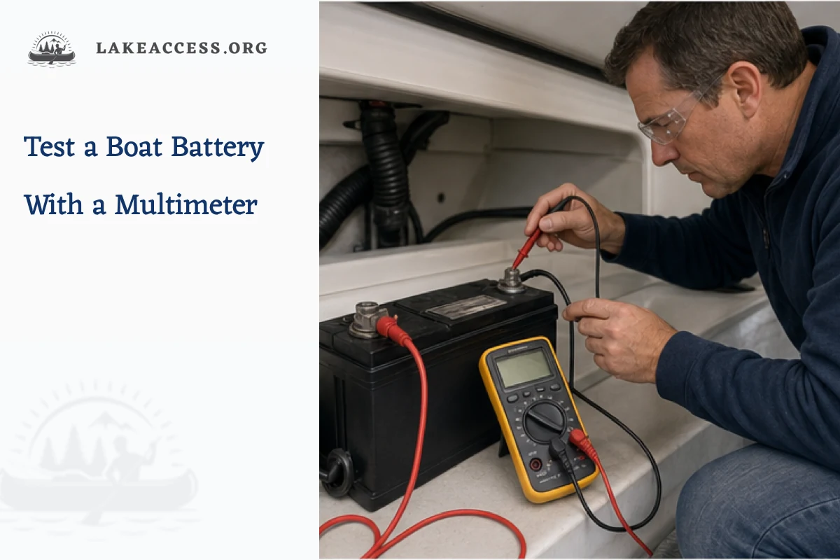
Quick answer: Set a sound multimeter to DC volts with the black lead in COM and red lead in the voltage jack, turn loads and charging sources off, ventilate the compartment, and measure directly across the secured battery terminals. A resting voltage is meaningful only after the battery has stabilized and must be interpreted with the battery manufacturer table for its chemistry and temperature. Voltage estimates state of charge; it does not by itself prove capacity or battery health.
Decision table
| Test | Condition | What it can show | Limit |
|---|---|---|---|
| Resting open-circuit voltage | Battery isolated and rested per manufacturer | Approximate state of charge for that chemistry | Does not measure usable capacity |
| Charging voltage | Compatible charger or engine charging system active | Whether charging voltage reaches the terminals | Target depends on chemistry and temperature |
| Cranking minimum capture | Meter and procedure rated for the task | Voltage behavior during a high load | Not a substitute for specified load testing |
| Voltage-drop test | Circuit operating under controlled load | Loss across cable or connection | Requires safe access and correct test points |
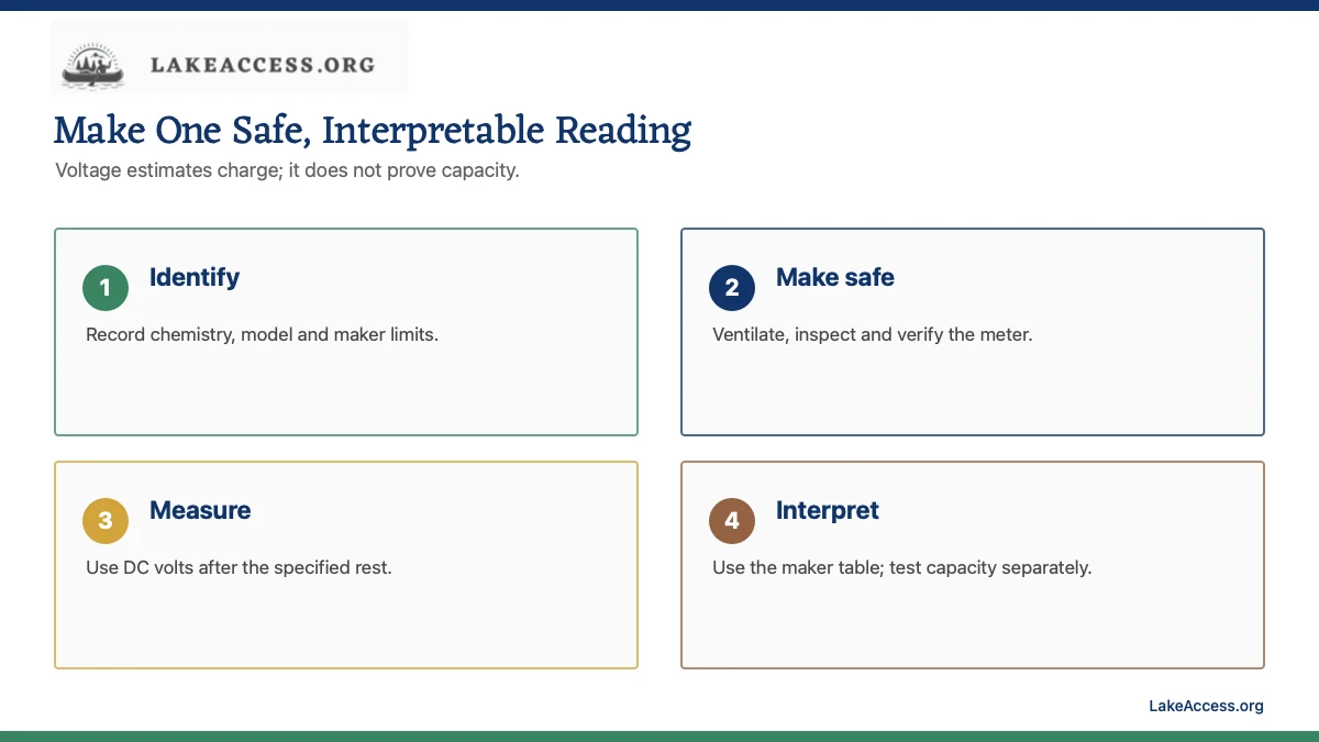
Identify the battery and make the area safe
Read the battery label for chemistry, nominal voltage, model and manufacturer. Flooded lead-acid, AGM, gel and lithium batteries use different charging and state-of-charge information. Do not apply a generic 12.6-volt rule to every chemistry or battery management system.
Ventilate the compartment and remove ignition sources. Wear the protection required by the battery maker, keep jewelry and tools away from terminals, and inspect for swelling, cracking, leakage, heat or a frozen battery. Do not test a damaged battery; isolate the area and follow the manufacturer or qualified technician procedure.
Inspect and prove the meter
Check the meter case, leads and probe insulation. Put the black lead in COM and the red lead in the voltage input, never the high-current jack for a voltage measurement. Select DC volts and a range above expected system voltage. Verify the meter on a known suitable source before relying on the result.
Keep fingers behind probe guards and prevent a probe from bridging a terminal to metal structure. A 12-volt battery has low nominal voltage but can deliver extremely high short-circuit current. Dry the work area and support the probes; do not hold loose metal tools above an uncovered battery.
Measure a stabilized resting voltage
Turn off loads and disconnect charging sources using the boat and battery manufacturer procedure. Trojan advises allowing a battery to stand open-circuit for about one hour for an accurate voltage reading. Other makers may specify a different rest period, temperature correction or method.
Touch red to the positive terminal and black to negative and record the reading, temperature, rest time and recent charge or load history. A negative sign usually means the probes are reversed. Do not scrape or force a probe into a corroded terminal while the battery remains connected.
Interpret the result by chemistry
Use the exact manufacturer state-of-charge table. Trojan publishes 12.84 volts as 100% and 12.24 volts as 50% for its listed AGM conditions, while other products can differ. Lithium iron phosphate voltage remains relatively flat through much of its state of charge, so the battery management system or shunt may be more informative.
A low resting voltage may mean discharged, undercharged, imbalanced or damaged; it does not identify the cause. Charge only with a compatible profile, then retest after the specified rest. For flooded batteries, manufacturer-approved specific-gravity testing may provide stronger state-of-charge evidence, but acid handling requires its own training and protection.
Check charging voltage without guessing targets
Reconnect or energize the charging source according to its manual and measure across the terminals while it operates. Compare the observed voltage with the battery and charger specifications for the current stage and temperature. A number that is normal for one chemistry can be harmful to another.
Watch for heat, odor, swelling, sparking or unstable readings and stop safely if any appears. Charging voltage at the battery does not prove the battery accepts rated capacity, and an alternator test around belts and moving machinery may require a qualified technician.
Know when voltage is not enough
A battery can show plausible open-circuit voltage and still fail under load because voltage alone does not measure capacity or internal condition. Use the manufacturer load-test or conductance-test procedure with appropriately rated equipment, or have a battery professional test it.
If batteries in a bank differ materially, isolate and test them using the system maker procedure rather than bypassing a battery management system. Diagnose cable voltage drop, parasitic draw and charging faults as separate tests. Do not replace a fuse, disconnect a live bank or switch meter functions while probes remain in place unless the instrument procedure explicitly requires it.
Work from a current circuit record
Identify every energy source, battery bank, charger, solar controller, alternator feed and shore-power connection that can energize the work area. Use the boat and equipment manufacturer shutdown procedure, confirm the correct disconnect points and prevent unintended reconnection. A switch label is not proof that a conductor is de-energized.
Update a one-line diagram with conductor gauges, protection devices, switches, returns and equipment models. Photograph existing routing before moving anything. Undocumented add-on wiring is common on older boats, so trace both positive and negative conductors rather than assuming color or destination.
Use marine-rated components and controlled terminations
Select conductor, terminals, fuse blocks, breakers, switches and enclosures for the system voltage, current, temperature, moisture, vibration and ignition environment. Tinned stranded copper is the normal marine choice for flexible DC wiring, but the component documentation and applicable standard control the installation.
Use the specified stripping dimension and a calibrated or verified crimp tool for the terminal. Inspect conductor strands before insertion, complete the required pull and visual checks, and support the wire so vibration and service access do not load the terminal. Do not solder a poor crimp or hide damaged strands under heat-shrink.
Separate voltage drop from overcurrent protection
Voltage-drop sizing is an operating-performance check. Ampacity and overcurrent protection are fire-risk controls. A conductor must pass both, and the fuse or breaker does not compensate for excessive voltage drop. Likewise, a conductor that delivers acceptable voltage can still be unsafe if it is undersized after derating.
Use actual round-trip length and measured or manufacturer load current. Confirm critical-circuit drop limits, engine-space temperature, bundles, insulation rating and terminal constraints. Protect conductors at sources as required, including additional sources created by battery banks or chargers.
Inspect the return path
A 12-volt device needs a complete positive and negative path. Corrosion, undersized returns and shared high-current connections can create voltage loss and unpredictable behavior. Include the negative conductor in length calculations and loaded measurements, and do not use an unverified metal structure as a substitute return.
Keep DC negative, AC grounding and bonding functions distinct in the diagram even where the applicable design connects them at defined points. Incorrect connections can create shock, corrosion or fault-clearing hazards. Complex multi-source and shore-power systems deserve review by a qualified marine electrician.
Commission under controlled load
Before energizing, inspect polarity, fuse type and rating, terminal covers, strain relief, conductor support, clearances and labels. Energize one circuit at a time. Measure source and load voltage while the device operates in a representative mode, and compare the result with design assumptions and equipment requirements.
Stop for abnormal heat, odor, noise, unstable readings, nuisance protection opening or visible arcing. De-energize before touching or tightening a connection. Thermal imaging can support an inspection when used correctly, but it does not replace torque procedures, voltage-drop measurements or direct examination of a suspect termination.
Keep service information with the boat
Label both ends of conductors and every panel position with durable identifiers. Record wire size, route, fuse class and rating, equipment model, test current, source voltage, load voltage and date. Keep spare fuses only in the exact approved types and protect them from moisture and loose metal objects.
Repeat the design review whenever a device, battery chemistry, panel or charging source changes. An empty switch position is not pre-approved capacity. Future work should begin from the updated diagram and measurements rather than reverse-engineering the same circuit again.
Define the measurement before taking it
Write what the measurement is intended to prove, the expected range, test points, operating condition and stop criteria. A voltage observed with the circuit off cannot prove loaded performance. A current measurement at idle cannot size a conductor for maximum sustained demand. A resistance measurement on an energized circuit can damage the meter or create a hazard.
Use an instrument and leads rated for the circuit and environment, inspect them before use and select the correct input jacks and function. Prove the meter on a known appropriate source when the procedure requires it. Keep exposed probe metal to the minimum needed, control body position and prevent a slipped probe from bridging positive to negative or grounded metal.
Record uncertainty and repeatable test conditions
Battery voltage, charging stage, equipment mode, ambient temperature and connection temperature can change a result. Record those conditions with the reading. When comparing source and load voltage, take readings close enough in time that changing battery or alternator output does not masquerade as circuit drop. A meter resolution digit should not be reported as installation precision.
Repeat an unexpected reading after making the circuit safe and checking test placement. Compare directly across a suspect connection under load to isolate its contribution. Do not pierce insulation or improvise an exposed connection unless an approved procedure and repair method exist. Protect the conductor after any authorized test access.
Design for inspection and fault isolation
Route and label conductors so a future technician can trace the circuit without removing unrelated systems. Keep protection devices visible and accessible while preserving required covers and environmental protection. Provide service loops only where they do not create unsupported weight, chafe or heat-retaining bundles.
Separate branch returns and positive feeds clearly enough that one device can be isolated and tested. Do not bury an inline fuse behind a sealed liner or place a connection beneath a likely leak. Good access reduces the temptation to bypass protection, cut an unknown conductor or diagnose by replacing parts.
Inspect for corrosion, chafe and heat over time
Commissioning is one snapshot. Add periodic checks suited to the boat, environment and equipment maker. Look for green or black conductor corrosion, swollen insulation, loose support, water tracks, cracked covers, fuse discoloration and terminals that have moved. Investigate an electrical odor or repeated reset immediately rather than waiting for the next schedule.
Compare loaded voltage and connection temperature with the recorded baseline when symptoms appear. A rising drop can reveal a deteriorating termination before equipment stops working. Replace damaged components with approved equivalents and repeat the full protection and performance review; cleaning a visible surface does not restore a corroded conductor hidden under insulation.
Compare batteries and connections consistently
When a bank contains multiple batteries, measure each only by the battery and system maker procedure and under comparable rest, temperature and connection conditions. A difference may justify further diagnosis, but it does not identify the failed component by itself.
Record voltage directly on the battery posts and, when safe and appropriate, at the cable terminals under load. A difference can reveal connection loss. De-energize before cleaning or tightening, and replace damaged cable rather than masking a hot or corroded termination.
Working checklist
- Identify battery chemistry, nominal voltage and manufacturer limits.
- Ventilate, remove ignition sources and inspect for damage.
- Verify meter, leads, input jacks and DC-voltage range.
- Record resting voltage only after the specified isolation and rest.
- Compare with the exact maker table and escalate to a proper load test when needed.
Related LakeAccess guides
- How long to charge a boat battery
- How to charge a boat battery on the water
- How to keep boat batteries charged
- Marine wire gauge guide
Sources
Standards, product instructions and safety information can change. These official or primary technical sources were checked on July 28, 2026; open the current source again before work.
- Fluke: Measure Battery Voltage With a Multimeter (checked July 28, 2026)
- Fluke: Test Lead Safety (checked July 28, 2026)
- Trojan Battery: Frequently Asked Questions (checked July 28, 2026)
- Trojan Battery: AGM Maintenance and Voltage Table (checked July 28, 2026)
- Trojan Battery: Guides and Manuals (checked July 28, 2026)
- OSHA: Battery Charging and Changing (checked July 28, 2026)
- USCG: Electrical and Battery Safety Circular (checked July 28, 2026)