

Quick answer: Create a three-dimensional weight ledger before installation: weight, longitudinal position, transverse position and vertical position for every structural item, tank, battery, appliance, person and movable load. Have a naval architect combine the ledger with hull geometry and credible tank and occupancy cases. Keep heavy items low and near approved structural locations only when the reviewed arrangement calls for it; simple left-right balance does not prove stability.
Decision table
| Decision point | Evidence to collect | Do not assume | Safe next step |
|---|---|---|---|
| Spreadsheet balances left and right | Verified vertical and longitudinal positions plus hull model | That symmetry proves adequate stability or trim | Run approved loading cases and check freeboard/downflooding |
| Fresh and waste tank levels trade places | Tank geometry, fill combinations, baffling and actual level method | That equal capacities cancel each other | Model each credible transfer state and free-surface effect |
| New roof equipment is proposed | Measured weight, support detail and height above baseline | That available payload permits high weight | Recalculate center of gravity, structure, wind and stability first |
| As-built draft or list differs | Lightship survey, onboard inventory and draft readings | That moving loose gear is a permanent correction | Stop, reconcile the ledger and obtain an updated assessment |
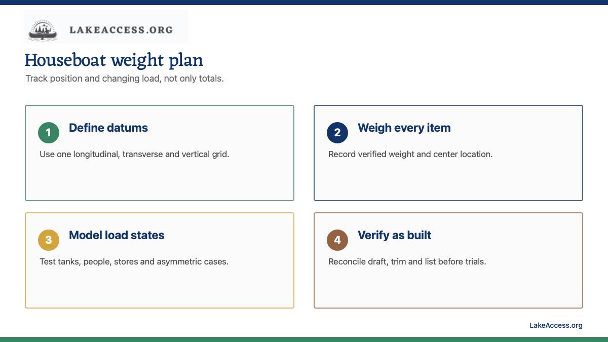
Use a coordinate grid and one datum
Choose a clearly defined longitudinal origin, centerline and vertical baseline from the reviewed drawings. Enter every item at its center of gravity, not at a convenient corner. Grouping an entire cabin at deck level can hide roof, window and appliance height. Use signed transverse positions so port and starboard moments do not disappear in a simple total.
Calculate longitudinal and transverse moments as weight times distance from the datum. A vertical ledger supports the center-of-gravity review, but the naval architect must combine it with hull buoyancy and stability. Lock formulas, units and revision numbers; one pound-feet column mixed with kilograms and meters can create a result that looks balanced but has no meaning.
Design permanent locations before buying equipment
Place tanks, batteries, generators, inverters, anchors and appliances only where structure, ventilation, access and system standards allow. Low and centered is a useful question, not a universal instruction: a heavy item can overload local framing, obstruct drainage, enter a fuel-vapor space or make service impossible. Obtain exact manuals and installation weights, including brackets, cables, fluids and enclosures.
Create reserved zones for variable stores and mark them aboard. Secure each item for vessel movement using the equipment and structural instructions. Do not rely on cabinetry friction. Keep escape paths and closures usable in every loading condition, and prevent occupants from gathering on a roof or deck area that the approved plan does not include.
Model the trip as a sequence of load states
Start with lightship, then add people, fuel, fresh water, waste, provisions, tender, anchors and movable gear. Run departure, mid-trip and return states, plus uneven tank use and people concentrated in credible areas. Include rain or water accumulation only as a casualty input defined by the designer, not as usable ballast.
Partially filled tanks require free-surface treatment. Never shift liquid between tanks to correct list unless an approved operating procedure expressly permits it. A persistent list can indicate flooding, trapped water, load movement or incorrect records. Bring people to safe positions, follow emergency procedures and stop operation rather than diagnosing by trial.
Reconcile the ledger through construction
Set weight checkpoints after hull completion, deck and cabin structure, systems installation and final outfitting. Weigh assemblies before installation and compare cumulative actual weight with the allowance. When growth consumes a margin, remove or redesign items before the vessel reaches the water; do not quietly reduce the assumed number of people after structure and systems are fixed.
At completion, perform the approved lightship survey or equivalent verification. Record installed equipment, tank states, draft, trim and list. Update the ledger and all loading instructions to the accepted as-built configuration. Keep a change threshold that triggers professional review after refits, and log every battery, appliance, furniture or roof change throughout the vessel's life.
Start with a design basis, not a shopping list
Write down the intended water body, operating season, maximum people, propulsion, cruising speed, range, overnight systems, dock arrangement, haul-out method and whether the vessel will ever be rented or carry passengers for hire. The answer changes structure, freeboard, stability, fuel, electrical, sanitation, fire protection and legal requirements. A lake-only personal vessel is not automatically exempt from design risk, and a component sold for marine use does not prove that the completed system is suitable.
Freeze a dated design basis before buying structural materials. Record the assumptions that control every later decision: fresh or salt water, expected wave and wind exposure, loaded displacement, tank locations, machinery, deckhouse height, openings, emergency egress and maintenance access. When an assumption changes, send that change back through the weight, stability, structure and compliance review rather than treating it as a cosmetic revision.
Separate concept arithmetic from engineering approval
Simple displacement arithmetic, a spreadsheet or a scale reading can expose an impossible idea, but it cannot establish adequate stability, scantlings, weld design, fatigue life, flotation performance or regulatory compliance. The U.S. Coast Guard Boatbuilder’s Handbook explicitly describes its compliance guidance as something other than a complete engineering manual. Use calculations in this guide as a way to organize questions for the responsible designer, not as authorization to launch.
A qualified naval architect or marine engineer should review a new or materially changed hull, especially when the project adds a deckhouse, rooftop equipment, large tanks, batteries, fuel, an unusual pontoon arrangement or passenger capacity. Give the reviewer measured weights, drawings, material certificates and the intended operating profile. A useful review produces controlling limits, loading conditions, test requirements and an as-built record, not only a general statement that the concept looks stable.
Build one traceable weight and equipment ledger
List every permanent and variable item with description, manufacturer, model, measured or documented weight, longitudinal position, transverse position and vertical position. Include hull structure, deck, cabin, windows, doors, roof, tanks, plumbing, wiring, batteries, appliances, furniture, propulsion, fuel, water, waste, anchors, safety gear, people and movable stores. Mark estimates clearly and replace them with scale tickets or manual values before the final analysis.
Keep a change log beside the ledger. A heavier refrigerator, extra battery bank or rooftop solar frame affects more than the purchase line: it changes displacement, trim, center of gravity, freeboard, structural loads and available payload. Photograph the item on a calibrated scale when practical and keep the source document. Weight control works only when the installed vessel and the spreadsheet describe the same configuration.
Protect freeboard, drainage and watertight integrity
Freeboard is the vertical distance from the waterline to the relevant deck edge or gunwale. Added weight reduces it, while heel or trim can bring an opening closer to the water. Identify the lowest downflooding points, including doors, vents, drains, hatches, plumbing penetrations and poorly sealed service openings. Do not count a decorative lip, untested seal or bilge pump as reserve buoyancy.
Rain, spray and shipped water need an unobstructed route overboard that does not rely on an undersized pump. Keep scuppers and freeing paths clear, avoid low pockets in the deck and inspect penetrations from both sides. A houseboat’s broad roof and enclosed accommodation can collect wind load and conceal leaks. Verify drainage and watertight closures in the real loaded attitude, not only while the empty hull is level in a shop.
Treat partially filled tanks as a stability input
Water, fuel and waste are variable loads. Their quantity changes displacement and trim, while liquid moving across a partly filled wide tank creates free-surface effect that reduces stability. A tank being low in the hull does not make this disappear. Tank geometry, baffling, fill state, orientation and restraint belong in the naval architect’s loading cases, and each tank needs a reliable means to determine its actual level.
Do not improvise internal baffles or alter a certified tank. Select equipment designed for its contents and installation, follow support and venting instructions and keep inspection access. Plan credible combinations such as full fresh water with an empty waste tank, the reverse condition, uneven consumption and people gathered on one side. An operating checklist should identify loading combinations that the design review prohibits.
Design structure and systems as interfaces
A deck panel, tank, battery tray, window, rail or appliance transfers load through attachments into surrounding structure. Verify the complete load path, fastener material, edge distance, backing, isolation, sealing and inspection access. Do not use a sealant as an undocumented structural joint, and do not drill a pontoon, hull, deck beam or pressure boundary merely because the fitting itself is labeled marine grade.
Electrical, fuel, ventilation, sanitation and fire systems have placement conflicts that must be resolved on drawings. Ignition sources need required separation or protection around gasoline fuel sources; batteries need restraint and terminal protection; plumbing needs serviceable valves and winterization access. Route conductors and hoses so normal movement, vibration and maintenance cannot abrade them against structure. Record every hidden run before closing walls or decks.
Control corrosion and moisture by compatible details
Dissimilar metals connected in a wet environment can create galvanic corrosion. Wood and composite cores can retain water after an unsealed penetration. Trapped moisture can attack a tank or fastener even when the visible finish looks sound. Select metals, coatings, isolators, fasteners and sealants as a compatible system for the substrate, immersion, ultraviolet exposure, temperature and future disassembly.
Follow the exact coating and sealant technical data for surface preparation, film thickness, cure conditions and material compatibility. More adhesive is not a substitute for correct joint design. Provide drainage and ventilation where the engineering calls for them, seal every core penetration and make high-risk interfaces inspectable. Keep batch numbers and product data with the build record so a later repair does not mix incompatible chemistry.
Plan construction inspection before closing access
Create hold points for hull dimensions, welds or bonds, structural framing, pressure or leak tests, tank installation, hose and conductor routing, electrical protection, ventilation, steering, propulsion, drainage and final loading. Photograph measurements with a scale and location reference. The person checking critical work should be competent for that process and independent enough to reject it before the next layer hides the defect.
An as-built package should show what changed from the reviewed drawings. Include material certificates, equipment manuals, receipts, inspection results, photographs, wiring and plumbing diagrams, weight ledger, test reports and maintenance intervals. This evidence supports registration, insurance, surveys, troubleshooting and resale. A folder of purchase receipts without installation and test evidence is not an as-built record.
Test in controlled stages
Complete shop checks before launch: fastener and attachment review, electrical protection tests, fuel and plumbing leak checks, steering travel, controls, alarms, ventilation, drainage and emergency access. The first launch should occur at a suitable facility with recovery capability, conservative weather and only essential personnel. Follow the naval architect’s test plan and stop criteria; do not use passengers or a public outing as ballast for an informal trial.
Progress only after resolving discrepancies. Record actual draft, trim, list, tank states, aboard weight and environmental conditions. A calm-dock result does not demonstrate behavior in wind, wake, turning or equipment failure. Sea or lake trials must remain within the design professional’s approved sequence and applicable agency requirements. Update the operating limits and as-built record with the accepted results.
Verify federal, state and local requirements separately
Federal construction and equipment rules, state titling and registration, local launch or marina rules, zoning, sanitation restrictions and insurance requirements are separate layers. The applicable rule depends on vessel length, propulsion, use, water, location and whether compensation is involved. Ask the named authority about the exact project and keep its current written instructions; another owner’s registration story is not controlling guidance.
Do not mark a homemade vessel with an invented manufacturer code or copy another hull identification number. Do not represent an imported or commercially produced hull as home-built. Confirm the state-assigned HIN process before permanent marking. If commercial use, rental, carrying passengers, liveaboard occupancy or a change of principal-use state is contemplated, disclose that early because it can change inspection, documentation, licensing and local permission.
Define stop conditions before spending more
Stop construction when the controlling drawings are absent, the calculated or measured weight exceeds the design basis, the hull sits with unexpected trim or list, freeboard is less than reviewed, an opening approaches the water, structure differs from the approved detail, materials cannot be identified, tanks or batteries lack rated restraint, or required inspection evidence is missing. Covering the work makes diagnosis harder and more expensive.
Also stop when agencies give conflicting instructions or an insurer, surveyor, marina and registration office require different evidence. Resolve the conflict in writing with the authority that owns each decision. A credible alternative may be a professionally designed stock platform, an existing certified hull or a smaller shore-based cabin. The safe result is not necessarily the design that preserves every feature in the first sketch.
Project checklist
- Define longitudinal, transverse and vertical datums.
- Record verified weight and center location for every item.
- Run departure, mid-trip, return and asymmetric occupancy cases.
- Account for partially filled tanks and downflooding points.
- Reconcile as-built lightship and issue approved loading instructions.
Related LakeAccess guides
- Choosing a houseboat floor plan
- Houseboat flotation basics
- Pontoon vs barge houseboat hulls
- Pontoon boat dimensions
Sources
Standards, agency procedures and product requirements can change. These official or high-trust sources were checked July 20, 2026; confirm the current rules and exact equipment before building, modifying or operating a vessel.
- Transport Canada Small Commercial Vessel Safety Guide (checked July 20, 2026)
- Transport Canada major modification and stability guidance (checked July 20, 2026)
- IMO ship design and intact stability overview (checked July 20, 2026)
- USCG simplified stability resources (checked July 20, 2026)
- 33 CFR 183.550 fuel tank installation (checked July 20, 2026)
- USCG Boatbuilder's Handbook electrical systems (checked July 20, 2026)
- 33 CFR Part 183 boats and associated equipment (checked July 20, 2026)